
This tutorial shows the process of importing a 3D model of a brake assembly into XVL Studio 3D CAD Corel Edition, then modifying the properties and settings to create an exploded view that can be imported into Corel DESIGNER as a 3D illustration.
Thanks for watching! We hope you found this tutorial helpful. You will find a written version of this tutorial below, and a printable PDF copy to download on the Download Resources tab above.
Download your FREE 15-day trial and expand what’s possible in visual communication with this comprehensive collection of software for high-impact technical design and documentation.
Download these free resources:
Written tutorial (PDF, 2 MB)
CorelDRAW Technical Suite resources
Corel DESIGNER User Guide (PDF, 22 MB)
CorelDRAW User Guide (PDF, 28 MB)
PHOTO-PAINT User Guide (PDF, 26 MB)
What’s New in CorelDRAW Graphics Suite
Technical Graphics Tutorials
 CorelDRAW Technical Suite
 Ultimate Vector Bundle Vol. 1
 CorelDRAW Graphics Suite
 Ultimate Vector Bundle Vol. 2
Converting a 3D Model to DESIGNER
In this tutorial, we’ll learn how to create an illustration of a 3D model in Corel DESIGNER. The model we’ll use is in SOLIDWORKS format.
In Corel DESIGNER, choose File > 3D Import, which opens XVL Studio 3D CAD Corel Edition.
To see what types of 3D files can be opened, choose File > Open and look at the available file types.
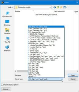
The formats without plus signs can be opened with XVL Studio Corel Edition, which is included in CorelDRAW Technical Suite, or with XVL Studio 3D CAD Corel Edition, which can be purchased as an add-on program.
The formats with plus signs can only be opened with the add-on XVL Studio 3D CAD Corel Edition.
If you have a file with a format that cannot be opened in the Corel version, you can convert it into an exchange format such as IGES, which can then be opened in the Corel version.
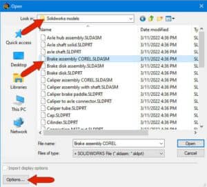
We’ll choose the SOLIDWORKS file format, select the “Brake assembly COREL” file, and click Options.
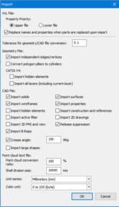
The Options window has options to filter the CAD data to import. In this example, we keep the default settings and click OK to import the model.
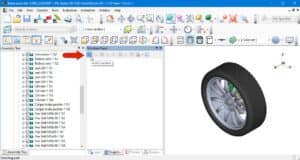
After a few seconds, the model is imported. With the Examine tool active by default, you can click and drag to rotate the model, zoom in and out with the scroll wheel, and press and hold the middle mouse button to pan.
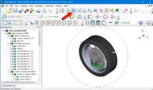
You can also display orthographic views by clicking the Front, Back, Right, etc. icons. We’ll return to isometric view.
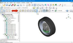
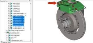
On the left, the Assembly Tree displays the structure of the assembly, sub-assemblies and parts. Selecting an object in the tree highlights it in the workspace, and after activating the Select Part tool, selecting an object in the workspace highlights it in the assembly tree.
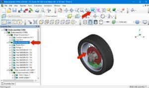
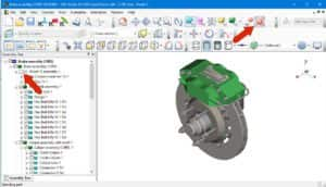
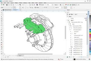
The green caliper appears at the bottom of the model, but we want it shown at the top. So first select everything by pressing Ctrl + A, then click the Move Part Icon.
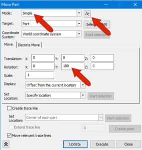
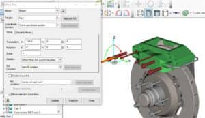
The Move Mode is Simple, and Part Selection is disabled so that the move will be performed on the parts that are already selected. Enter a 180-degree rotation about the Y axis, then click Execute and Close at the bottom.
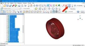
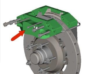
The caliper should now appear at the top, on the back side of the assembly.
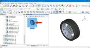
In order to preserve this position, we can take a snapshot. Choose View > Panel > Structure Panel and click the Camera icon at the top of this panel.
Now if you move or rotate the object, you can double-click Snapshot 1 listed in the Structure Panel to return to the position you just saved.
Now let’s set up the model the way we want it to appear in Corel DESIGNER, as an exploded view.
At the top of the Assembly Tree, uncheck “wheel 15 assembly-1″ to hide it, then click Fit Selection to zoom the visible parts to fit the workspace.
Click Select Part again and hold down the Shift key while selecting each of the six bolts at the top of the caliper assembly.
To bring back the Move Parts window, press Ctrl + M. Rather than specify a direction and distance, you can simply click and drag along the X axis to move the bolts away from the assembly.
While the Move Part window is still open, select the front half of the caliper and move this part out in the X direction as well.
You could continue to separate parts this way, but let’s leave just these moved parts, and close the Move Part window.
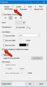
Before sending to Corel DESIGNER, let’s set some conversion options for the parts. The entire model is to appear as thick and thin lines, with the caliper front filled with its original green color to make it stand out. Select and right-click the front part of the caliper and choose Properties.
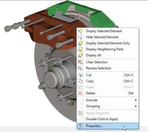
On the Shell Display tab, check Apply shading to hidden line images. Then click Set, and Close.
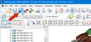
Now we can click the Send to Designer icon.
In the Send to Corel DESIGNER window, we’ll set the illustration frame size to 250 x 250 mm, then drag and zoom so that the parts fit entirely inside the frame. For more options, click Details.
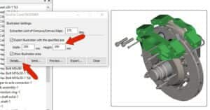
The Details window has enhanced export options for the add-on XVL Studio 3D CAD Corel Edition, which are not available in XVL Studio Corel Edition that is included in CorelDRAW Technical Suite.
On the Style 1 tab you can set the thick and thin line properties. The Silhouette Line and Independent Edge are both 0.6 mm to make their thickness easier to see, and the Concave and Convex edges are 0.2 mm. The 2 Extraction Limit fields set the level of line detail, and the effect of these values depends on the geometry. In this example we set both to 175.
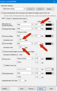
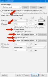
On the Style 2 tab, you can set the options for the filled caliper. In this example we enable the Outline and Outline each part options, as well as the Color parts (SVG only) option. Both Target fields are set to Use shell display settings.
Once the settings are complete, click the Send button at the bottom of the window. This adds a new snapshot that represents the import view, which you could return to in XLV Studio if you need to change the import contents or settings.
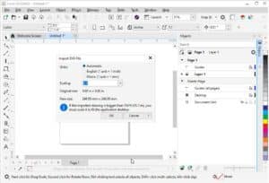
After a few seconds of processing, Corel DESIGNER will display import settings. In this example, we keep the default settings and click OK to import.
You can click and drag to place the imported illustration, or press Enter to center it on the page.
In the Objects docker, we can expand the groups to see how each assembly, sub-assembly, and part was converted to a group of curves. The caliper curves are filled, and all curves have thick or thin line widths.
Start your FREE 15-day trial and embark on a design journey with powerful tools for vector illustration, layout, photo editing, typography, and collaboration.