
The Perspective Drawing feature, introduced in CorelDRAW 2021, enables you to create 3D-looking objects in 1, 2, or 3-point perspective, without needing to set up complex grids. In this tutorial we will show you how to work with the perspective field and draw directly in the plane you want, or place existing orthographic objects onto a perspective plane.
Thanks for watching! You will find a written version of this tutorial below, and a printable PDF copy to download on the Download resources tab above.
Start your FREE 15-day trial and embark on a design journey with powerful tools for vector illustration, layout, photo editing, typography, and collaboration.
Download these free resources:
Written tutorial for Windows (PDF, 2.1 MB)
Written tutorial for Mac (PDF, 2.2 MB)
CorelDRAW Graphics Suite resources
Quick Start Guide (PDF, 2 MB)
Keyboard Shortcuts (PDF, 3.5 MB)
CorelDRAW and Corel PHOTO-PAINT user guides
For CorelDRAW Graphics Suite subscription and perpetual licenses (2018 to 2024), languages include English, Português do brasil, 简体中文, 繁體中文, Čeština, Deutsch, Español, Français, Italiano, 日本語, Polski, Русский
CorelDRAW Community
CorelDRAW learning center
Facebook
X (formerly Twitter)
YouTube
What’s new in CorelDRAW Graphics Suite
Lines, shapes, and outlines
CorelDRAW tools
 CorelDRAW Graphics Suite
 Ultimate Vector Bundle Vol. 1
 CorelDRAW Standard 2021
 Ultimate Vector Bundle Vol. 2
 Corel Vector
How to draw in perspective
The new Perspective Drawing feature, introduced in CorelDRAW 2021, enables you to create 3D-looking objects in 1, 2, or 3-point perspective, without needing to set up complex grids. In this tutorial we will show you how to work with the perspective field and draw directly in the plane you want, or place existing orthographic objects onto a perspective plane.
Click on any of the images below to view full-size.
Introduction to perspective drawing
Let’s start with an overview of the perspective views. One-point perspective, with its single vanishing point, can be used to simulate a view along a road, in which everything shrinks toward a point in the distance.

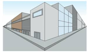
Two-point perspective can be used to show a view from a corner, such as in this example of buildings that each shrink toward vanishing points off to the side.
Two-point perspective can also be used to showcase a packaging design.

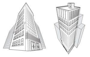
Three-point perspective is generally used for more dramatic views that focus on the top of an object that vanishes toward the bottom, or vice versa – to show how objects look from below.
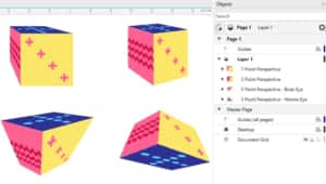
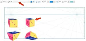
The following four objects demonstrate the four types of perspective drawing: one-point perspective, two-point perspective, and two versions of three-point perspective – bird’s-eye view and worm’s-eye view. Perspective objects are in their own groups, and multiple different perspective groups can exist in the same document.
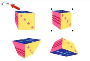
When a perspective group is selected, the Edit button appears at the top left, and the Edit Perspective Group option is also available in the object’s context (right-click) menu.
When you enter editing mode for a perspective object, the Perspective Field is displayed. The perspective field can be selected and enlarged as needed, to display the horizon line and both vanishing points of this two-point perspective object.
How to create perspective drawings
There are two workflows you can use to create perspective drawings: moving existing objects onto perspective planes; and drawing objects from scratch in perspective.
Method 1: Moving objects onto perspective planes
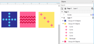
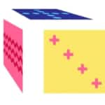
In this example, three rectangles will be used to build a perspective cube. Each rectangle is part of a group, which also contains the objects inside the rectangle. When moving objects to a perspective plane, it’s much easier to work with a single group than with separate, individual objects.
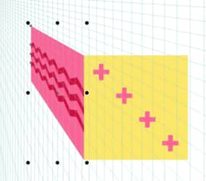
Go to Object > Perspective > Draw in Perspective. On the perspective toolbar, choose a perspective type from the Type list box. We are starting with One-point perspective.

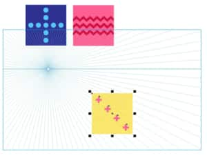
Now you can drag to place the perspective field, or press Enter to fill the entire page.
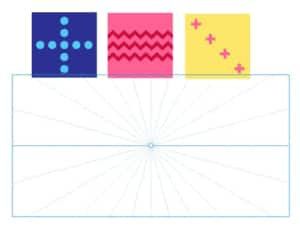
You can move the vanishing point, raise or lower the horizon line, and adjust the density of perspective lines.
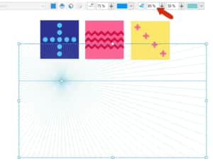
The perspective toolbar also has options to toggle on and off the horizon line and perspective lines, change their colors, or adjust their opacity. Camera lines are off by default but can be turned on, and the perspective field can be locked, to prevent any accidental changes.
Under Snap To on the standard toolbar, make sure that snaps are enabled for Objects, and you can also turn on snaps for Perspective Lines.
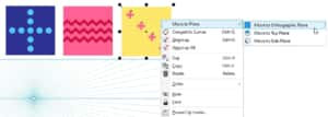
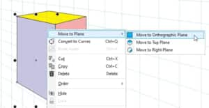
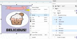
The yellow group will be the front of the cube and will remain in the orthographic plane. All perspective objects need to be moved to a perspective plane, so right-click on the object and choose Move to Plane > Move to Orthographic Plane.
Select the object and move it into the perspective field, below the horizon line.
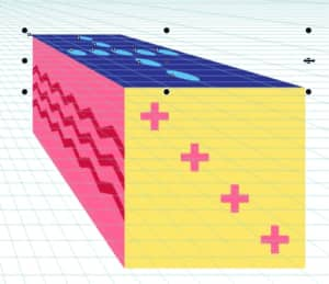
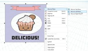
The pink group will become the side of the cube, so right-click on it and choose Move to Plane > Move to Side Plane. The perspective lines now follow the side plane, and when moving this object, its edges follow the perspective lines.
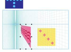
You can use the handle on the lower front corner of the rectangle to line up this corner with the yellow front face.
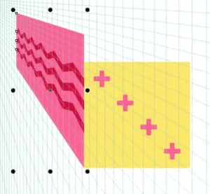
This side object is a bit too large, so we can use top corner handle to scale it uniformly inward from the opposite corner.
The blue group will go on top, so we right-click on it and choose Move to Plane > Move to Top Plane. After moving the object and connecting the corner node, we can use the side handles to resize in two directions.
Selecting an object on a perspective plane activates that plane and its perspective lines, so it is easy to adjust, such as resizing the side and top objects to make them a bit shallower.
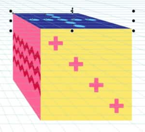
When all looks good, click the Finish button to exit perspective drawing mode.

This entire cube is now its own perspective group, comprised of the three original square objects.
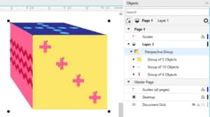
When a perspective group is selected, you can click the Edit button in the top left corner, to return to editing in perspective.
A perspective group can be moved or scaled uniformly, but other tools are grayed out, such as Rotate and Mirror. This is because those tools would break the relationships between objects on different planes.
Finally, if you wanted to manipulate the various objects inside the perspective group, you’d first have to break apart the perspective group, then ungroup.
Method 2: Drawing perspective objects from scratch
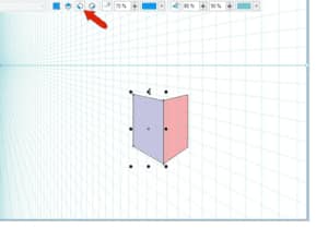
Next, we’ll draw directly in perspective. In a blank document, go to Object > Perspective > Draw in Perspective, and choose Two-point from the Type list.
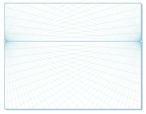
Press Enter for a full-page perspective field, raise the horizon line, and increase the field density.
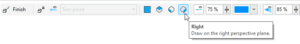
To start drawing on the right side, click the Right icon.
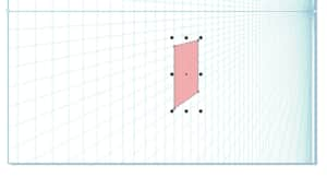
This changes the perspective lines to match the right plane. Now with the Rectangle tool, draw the right side of the box.
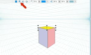
The next rectangle will be along the left. You can snap to one corner and adjust the other edge to fit.
Finally, add the top rectangle – in this plane you can snap to both corners.
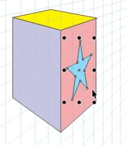
For simple vector objects, such as a rectangle, ellipse, or star, you can first activate the plane, then draw directly in perspective.
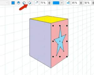
Or you can switch to the Orthographic plane to draw the star, then move the star to the plane where it will go.
Then you can move the star into place.
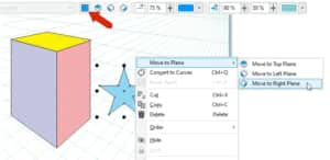
But for more complex objects, it’s usually better to work in orthographic view. So with the left side selected, move it to the Orthographic plane.
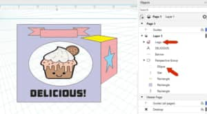
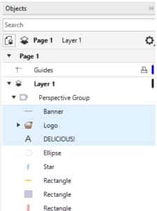
Now you can add what you want, such as text or a logo, or a common shape. In this example, the ellipse was added directly to the perspective group because it is a simple shape. The banner, logo, and text were added outside the perspective group.
Any objects outside the perspective group must be added to one of the planes. So with these three objects selected, move them to the Orthographic plane, to match the rectangle on which they’re placed.
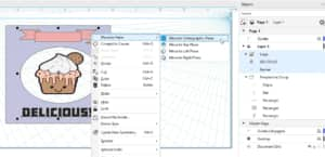
Now these objects are inside the perspective group.
So that the entire side of the box will act as one object, add the rectangle and ellipse to what’s selected, and group all objects.
Now you can move this entire group to the left plane.
After clicking Finish to end perspective editing, everything on all sides of the box is in the correct location and orientation.

Perspective drawing and 2D drawing
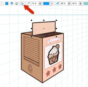
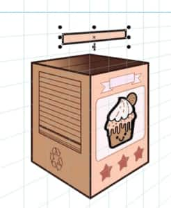
In some cases, you may have to combine perspective drawing with 2D drawing to get the look you want. This example shows two sides of a carton in perspective, and we want to add the triangular top.

You can start the top part by drawing a rectangle across the middle of the box, while in the Right plane.
Resize to push this rectangle up a bit, so that what remains will be the very top of the carton.
Now switch to the Orthographic plane and use the Pen tool to create this four-sided shape.
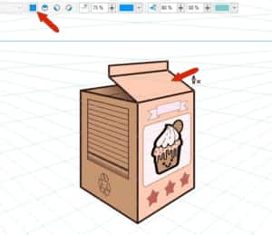
Use the same tool for this small triangle in the back.
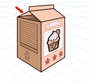
These two closed shapes aren’t actually perspective objects, but because they are associated with a plane, they remain inside the perspective group.
You can add more objects to these new faces, using CorelDRAW’s rotating and skewing tools to simulate the perspective look.

Start your FREE 15-day trial and embark on a design journey with powerful tools for vector illustration, layout, photo editing, typography, and collaboration.