
This tutorial will demonstrate how to use Style Sets in Corel DESIGNER to ensure a consistent look, style, and layout throughout your design projects. Style sets enable you to quickly apply a set of properties to one or more objects, and changing a style set updates all items to which that style set has been applied. Style sets also make it easy to comply with drawing standards such as S1000D.
Download your FREE 15-day trial and expand what’s possible in visual communication with this comprehensive collection of software for high-impact technical design and documentation.
Download these free resources:
Written tutorial (PDF, 908 KB)
CorelDRAW Technical Suite resources
Corel DESIGNER User Guide (PDF, 22 MB)
CorelDRAW User Guide (PDF, 28 MB)
PHOTO-PAINT User Guide (PDF, 26 MB)
Technical Graphics Tutorials
What’s New in CorelDRAW Graphics Suite
 CorelDRAW Technical Suite
 Ultimate Vector Bundle Vol. 1
 CorelDRAW Graphics Suite
 Ultimate Vector Bundle Vol. 2
Working with Style Sets in Corel DESIGNER
There are three dockers we’ll be using in this tutorial: Properties, Object Styles, and Projected Axes. Dockers can be opened via the Window menu, or you can use the Add icon below the docker tabs.
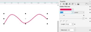
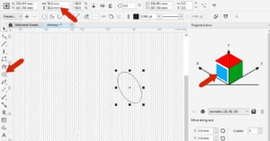
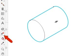
Draw a curve with the Bezier tool, and leave the curve selected. You can use the Outline tab of the Properties docker to change outline color, width, or line style. There are also tabs to set Fill, Transparency, and other properties.
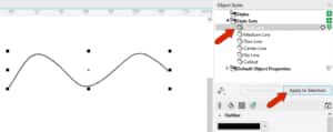
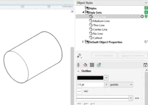
With style sets, you can avoid having to manually apply each individual property. In the Object Styles docker, there are several style sets already defined, configured for use in technical illustration. You can also create your own style sets, which we’ll see farther on. Choose Thick Line, whose properties appear just below, and click Apply to Selection.
There are also keyboard shortcuts for applying the default style sets. Ctrl + Shift + 1 applies Thick Line, Ctrl + Shift + 2 applies Medium Line, use 3 for Thin Line, 4 for Center Line, and 5 for No Line.
In the Properties docker, you can see that the properties match those of the style set.
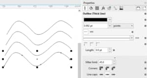
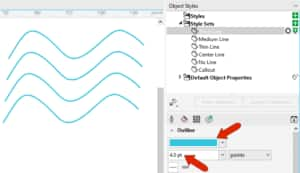
Press Ctrl + D to make a few duplicates of the curve, which all have the same properties. Returning to the Object Styles docker, update the outline width and color for Thick Lines. This changes all curves because they all have this style set applied.
Now let’s look at using the Thick Line and Thin Line styles sets in a parallel perspective drawing of a bolt.
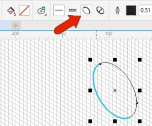
Choose View > Grid > Document Grid, or press F10, and open the Projected Axes docker. Activating the blue plane adjusts the grid and drawing tools to that plane. Draw a Center Point Circle with a 50 mm diameter.
A common technique in technical illustration is to assign thick lines to outer edges and thin lines to inner edges. This can be done by enabling Thick and Thin lines, and the Thick Line style you edited before is now applied to the thick part of the circle. The Thin Line style is applied to the rest of the circle.
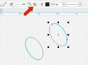
Returning to the docker, set a 90 mm distance in the Z axis, add one copy, and click Apply to create the back of the bolt.

The outer part of this circle should be thick, so click Reverse line width.
Now turn off the grid and use the 2-Point Line tool with the Tangential option to connect the two circles.
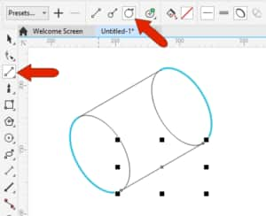
Select both lines, and in the Object Styles docker, the Thick Line style set should still be selected. You can click Apply to Selection or double-click the style set name to apply it.

To clean up the drawing, use the Virtual Segment Delete tool to remove the part of the circle at the back of the bolt that wouldn’t be seen in a 3D drawing.
The final drawing will look better with thick edges that are black and a bit less thick, so make these changes to the Thick Lines style set, which updates all thick lines at once.
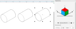
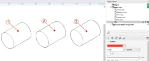
In the Projected Axes docker, clicking in blank space returns to Orthographic drawing mode. Select the entire bolt and make two duplicates.
In addition to the default style sets, you can also create your own.
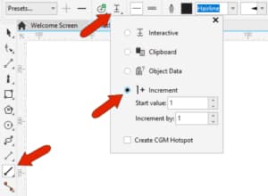
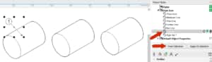
Activate the 1-Leg Callout tool. To set up automatic numbering, click Text Source and choose Increment which starts the numbering at 1.
Drag to apply the callout to the first bolt, and keep the callout selected. In the Properties docker, open the Outline tab and change the arrowhead to a dot. Use the Halo tab to widen the halo, use the Text tab to change the number font and size, and use the Callout tab to add a circle around the number.

Pressing the spacebar returns to the Pick tool and the callout is still selected. In the Object Styles docker, click From Selection, which creates a new style set that includes all properties of the selected object. Name the new style set “Callout.”
Clicking the gear icon opens the list of property categories that correspond to the tabs that appear below, such as Outline or Fill. You can display more tabs if needed, or close tabs.

There is also a Delete icon for the style set, though the default style sets cannot be deleted.
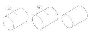
Now when you add a callout to the next bolt, the incremental numbering is correct, and to apply the new style set, click Apply to Selection.
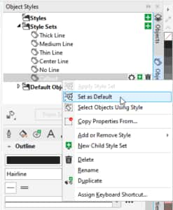
If you don’t want to apply this style set for each new callout, you can right-click on the style set and choose Set as Default.
Now the third callout automatically has the correct properties.
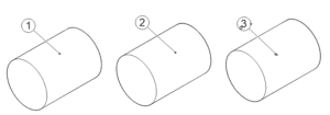
And if you want these callouts to stand out a bit, simply adjust the outline color and width for the style set.
Keep in mind that new style sets you create only exist in the current document. To save the Callout style set as a default for future documents, click Import Export and choose Set as New Document Defaults.

Then choose Styles Sets and click OK.
Download your FREE 15-day trial and expand what’s possible in visual communication with this comprehensive collection of software for high-impact technical design and documentation.